The Crazy Control Panel
It is indeed a crazy control panel! Why? Because Andy's wife would prefer he doesn't buy a commercial aircraft or a 60's era space capsule. To satiate his need to push buttons, flip switches and monitor blah-blah-blah levels, he designed and built a control panel any NASA pilot would be right at home in front of.
The Panel Outside
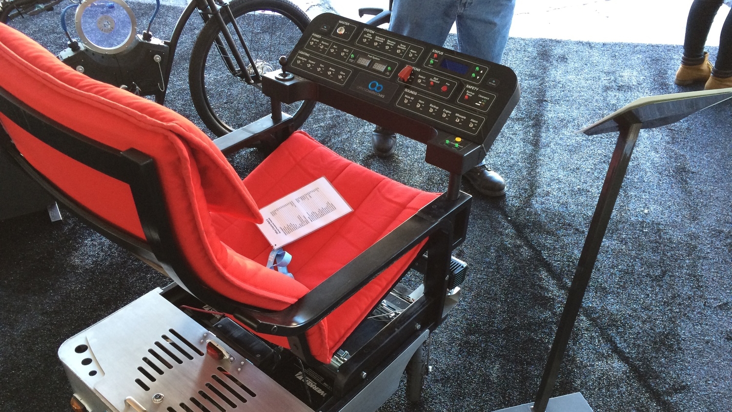
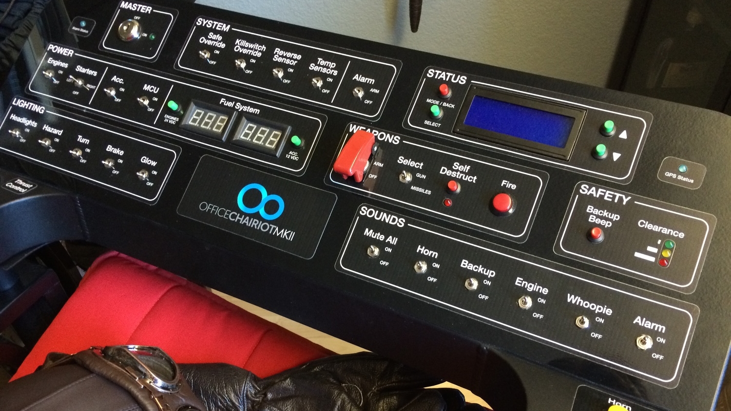
The panel has over 30 switches and buttons. There's a "Master" keyswitch, a LCD for status output and configuration changes, two battery voltage meters and, of course, the "Thrust Control" joystick. Sprinkled around the panel are a handful of LEDs of varying colors, as well.
The enclosure itself (or the body of the panel) is powder-coated aluminum. It was designed around the face of the panel which was initially designed in Adobe Illustrator. The Illustrator file was converted to DXF and sent to the fabricator, Liquid Metal Concepts in Phoenix, AZ, where they extruded it in SolidWorks and had the aluminum cut on a waterjet at Southwest Waterjet and Laser, also in Phoenix. They then bent and welded the enclosure together, added some threaded holes and made a backplate with posts and matching mounts to mount it on the chair.
The face of the panel is actually a separate piece of black plastic cut on a laser with the exact same DXF file. The graphics on the face of the panel are vinyl decals made from the exact same process as automotive graphics wraps. I had those made at Sign-A-Rama in Tempe, AZ. Basically, the labels on the face of the panel are peel-n-stick vinyl custom-printed decals. That vinyl doesn't stick well to matte-finish powder-coated surfaces, as it turns out. This is why they're stuck to that piece of plastic. The plastic face is being held onto the aluminum enclosure by all of the switches and buttons. It actually turned out to be a nice fit-n-finish.
The Panel Inside
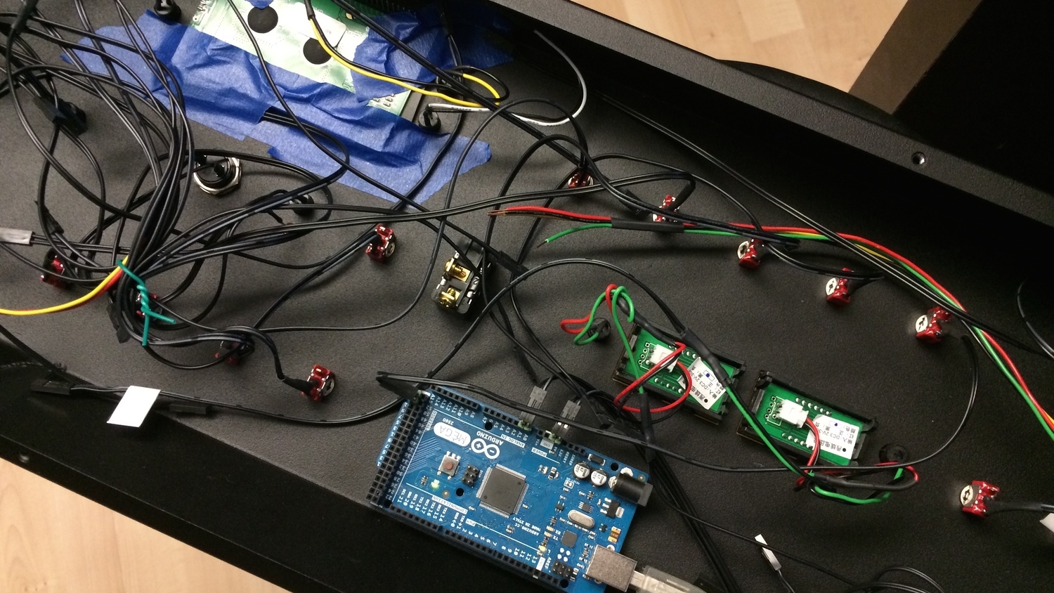
The panel, like the chassis, is controlled by an Arduino Mega 2560. It was chosen for the amount of program memory it has, 256K, and the number of available I/O pins. The panel has a lot of accessories that require I/O pins and that, in turn, means the firmware to manage all of those accessories requires more memory.
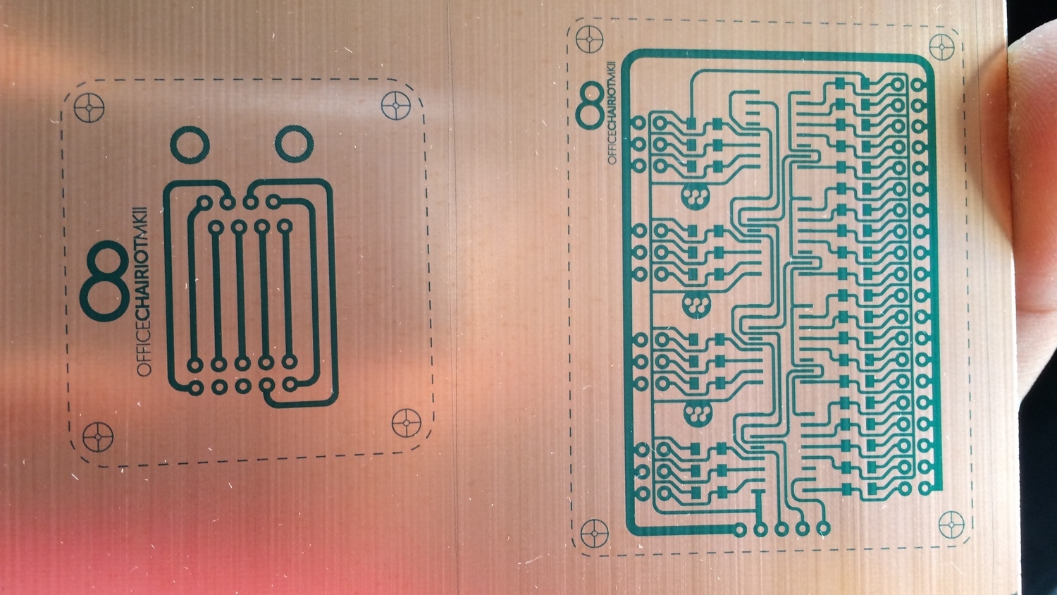
To lower the number of pins required by simpler things, like all those switches and buttons, a custom-built printed circuit board was built. It contains shift registers that allow the Arduino to gather the states of all of the buttons and switches in one fell swoop using only a couple of pins.
The USB port for the Arduino is brought out to the back of the panel with a cool little panel-mount port for convenience of reprogramming it and to communicate with it (monitor debugging info and stats). Makes the control panel look like a real USB device, too. Funny.
The various LEDs on the panel are controlled the same way as the buttons and switches. They are all connected to an LED controller similar to a shift register. It allows the Arduino to turn LEDs on and off by shifting bits out to the little controller board.
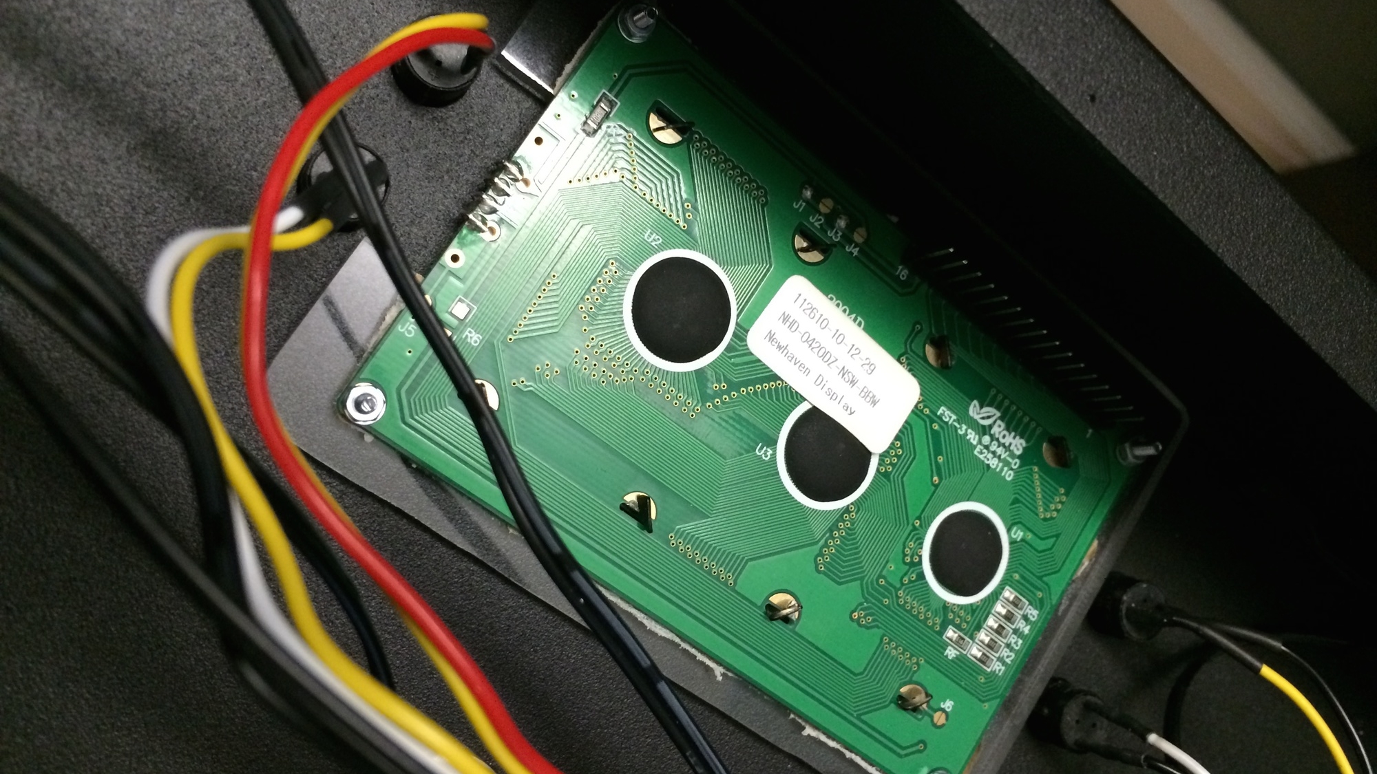
The LCD is connected with an 8-bit parallel interface for faster output. There is another custom-built daughter board on the back of the LCD that handles power, brightness and contrast. There is a digital potentiometer on the board for controlling the the contrast of the LCD. The backlight brightness is managed through PWM via a MOSFET on the board.
The Panel Firmware
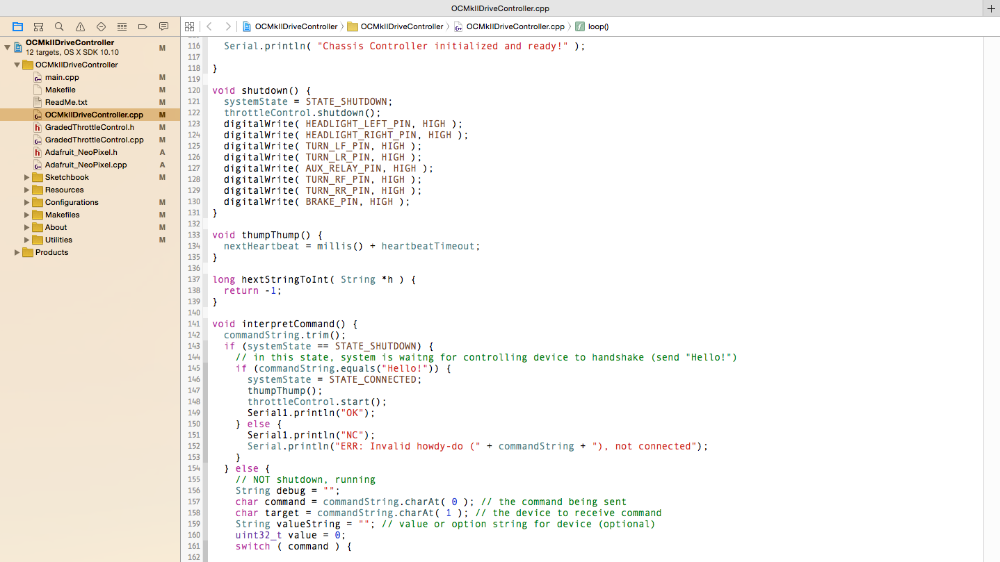
In a little while, all of the source code for the Office Chairiot Mk II, both the SmartChassis and the control panel, will be available on Bitbucket.org or GitHub. It's been written to be easy to follow and understand. There is a lot of C++ class work in there and input from other developers is always welcome.