The Office Chairiot Mk II SmartChassis
Let's start with the chassis: The base of the Office Chairiot Mk II is actually more akin to a battle robot for a couple of reasons: It's got a heavy-duty wooden frame (soon to be replaced by an all aluminum frame) (stayed tuned to this website for updates) and a swanky aluminum body. It wheels around on pneumatic scooter tires for a smooth ride, even in parking lots and loose gravel. It has very few moving parts because of the differential steering. Motors, chains, sprockets, casters and wheels make it go.
The Chassis Outside
As mentioned above, the core of the Office Chairiot Mk II's chassis is made of two pieces of 3/4" plywood and a few pieces of 2x4 pine. It was a valid choice for a maker who couldn't weld. There's plenty of wood in there to keep it sturdy.
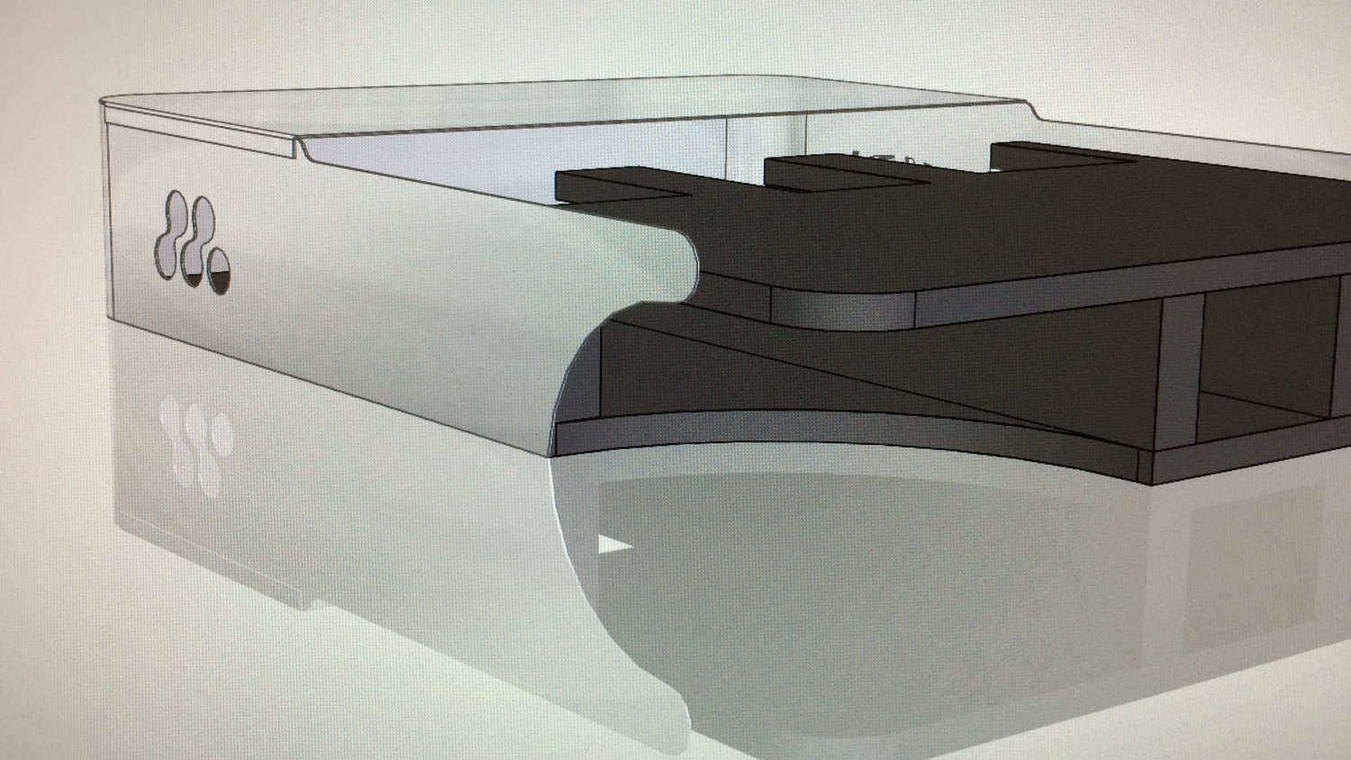
The body is made of sheet aluminum. The pieces were cut on a waterjet at the Local Motors Labs in Chandler, AZ. CAD for the pieces was done in Solid Edge on the workstations at Local Motors and in ViaCAD 9 Pro on the StuffAndyMakes.com Mac Pro.
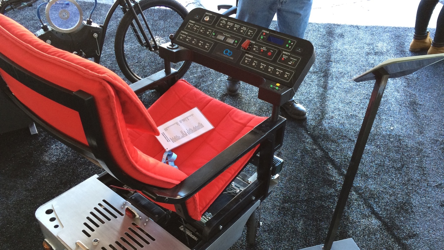
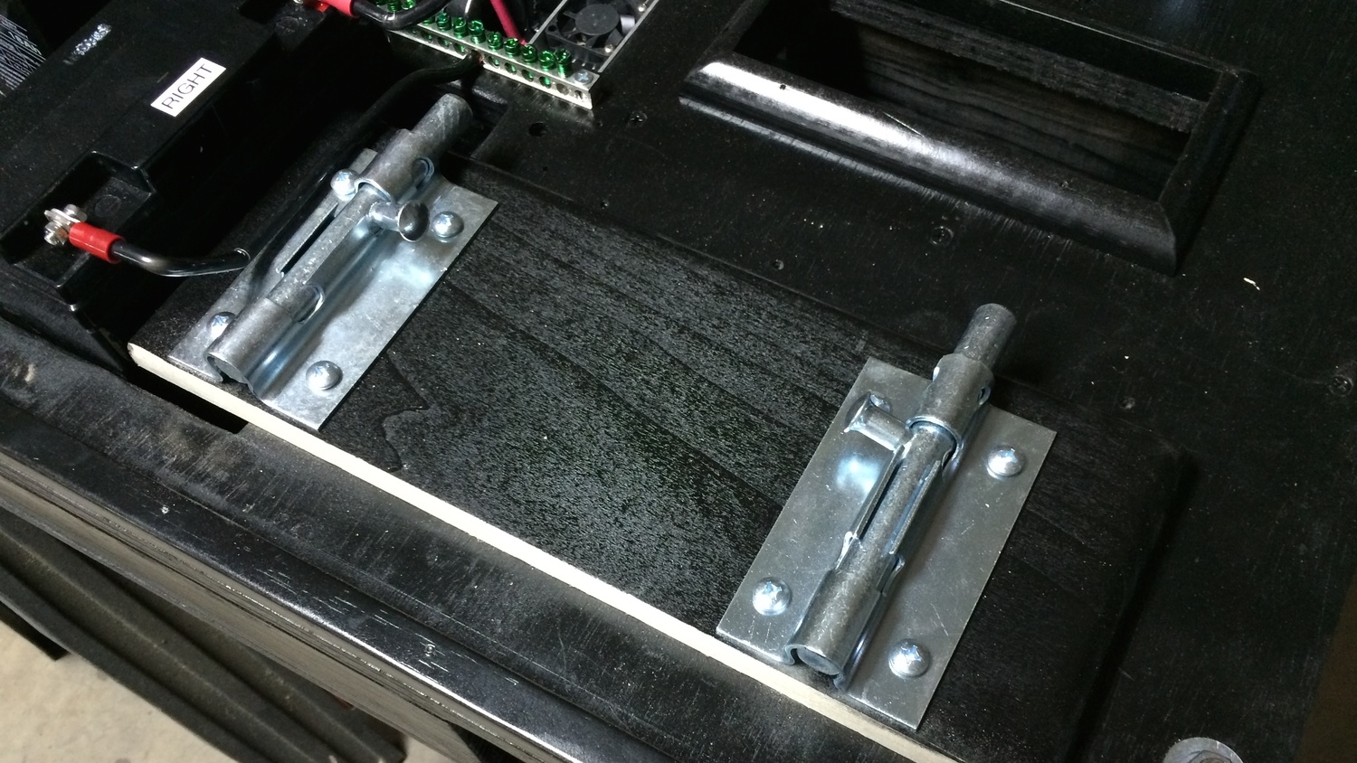
The IKEA chair and other accessories are connected to the chassis using four incredibly strong fence latches which make switching accessories very fast and easy. This simple system is called, "QuickLatch." A video of the system in action is coming shortly.
Every tire on the chassis is a pneumatic scooter tire to help smooth out the ride over rougher terrain. The front wheels on the chassis are simple, but heavy-duty casters holding air-filled tires. The rear wheels are actual rear wheels for motorized scooters with freewheeling sprockets that have been welded into place to prevent freewheeling.

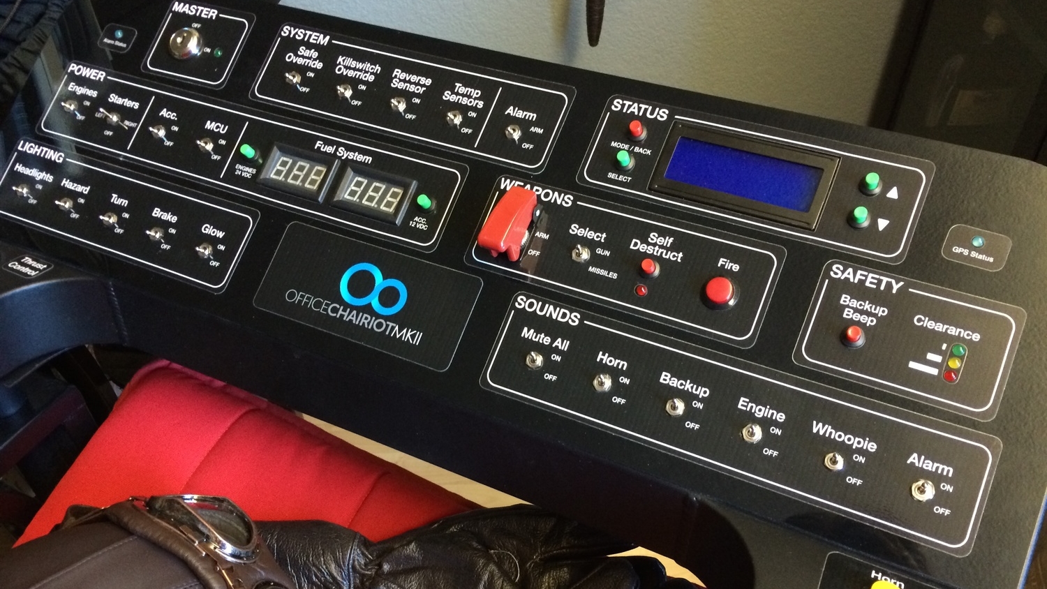
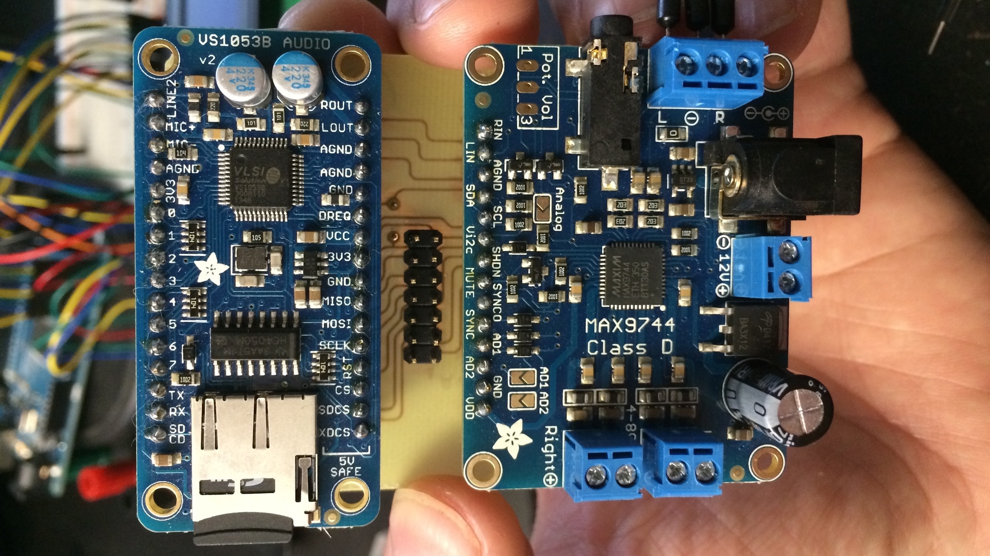
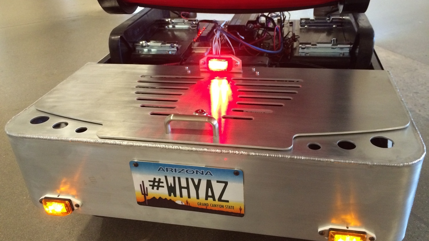
The chassis is loaded with LED lighting features, including headlights, turn signals, a brake light and fully-programmable RGB LED lighting under the chassis and behind the logos cut into the body side panels. Each light is individually controllable by the chassis microcontroller via a relay board. The current draw can be quite impressive, considering there are 72 RGB LEDs underneath, another 16 behind the logos, two very bright headlights and 5 smaller indicator lights.
The Chassis Inside
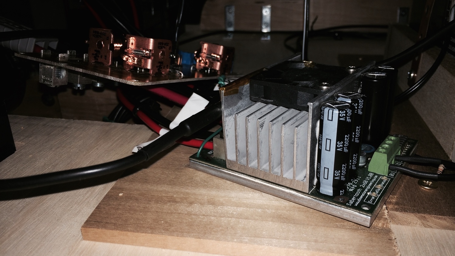
Remember that bit about the battlebots above? In fact, this chassis uses a motor controller used in beefier battlebots: The Dimension Engineering Sabertooth 2x60 motor controller. It's capable of carrying 1,000 lbs. of cargo and can feed the drive system up to 60 amps per motor channel (and even short bursts of over 100 amps). It has many command modes, but in our case, it's being used in simple serial mode.

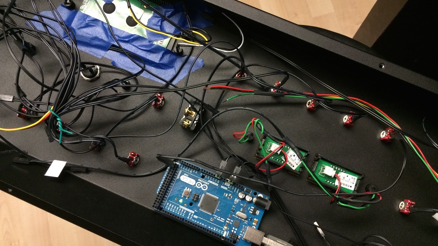
The main brain on the chassis is an Arduino Mega 2560, an 8-bit, 16 MHz (1 MIPS) prototyping board based on the Atmel® ATmega 2560 microcontroller. The Arduino takes commands from any number of different kinds of remote controls over its UART (serial port) and translates a simple protocol of characters and bytes into motor commands, RGB LED and relay control.
The Arduino can also report on a number of on-board sensors, giving the remote control access to helpful data points on such things as motor temperature, power wire temperature, ambient air temperature, wheel RPMs, accelerometers, seat occupancy and GPS data.
The Chassis Firmware

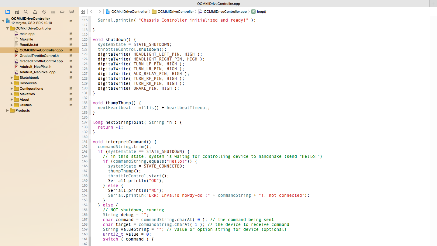
The firmware is written in C++ in Apple's Xcode IDE which is made to play nicely with Arduinos and other embedded boards by a killer utility called, "embedXcode" from Rei Vilo Hobbies. embedXcode reconfigures Xcode to make Arduino development (among other embedded environments) super easy to do in Xcode. If you've never seen Xcode and you're on a Mac, once you see it, you'll never go back to the Arduino/Wiring IDE. Xcode is a FREE, high-end integrated development environment normally for writing Mac OS X and iOS applications. It's loaded with incredible and, by today's professional software development standards, expected features and functionality. The code indexing and code completion along are worth getting that set up. Syntax coloring, line numbers, error highlighting, etc. are all available to you in this environment. WAY better than the Arduino/Wiring IDE.
Handshakes & Heartbeats
The chassis firmware is meant to be simple. It's also meant to be safe. The chassis expects a connected remote controlling device to follow a simple character and byte protocol over a serial connection. It also expects to hear from the controlling device twice every second, otherwise it will shut down the motors (for safety) and lights (to save battery power).
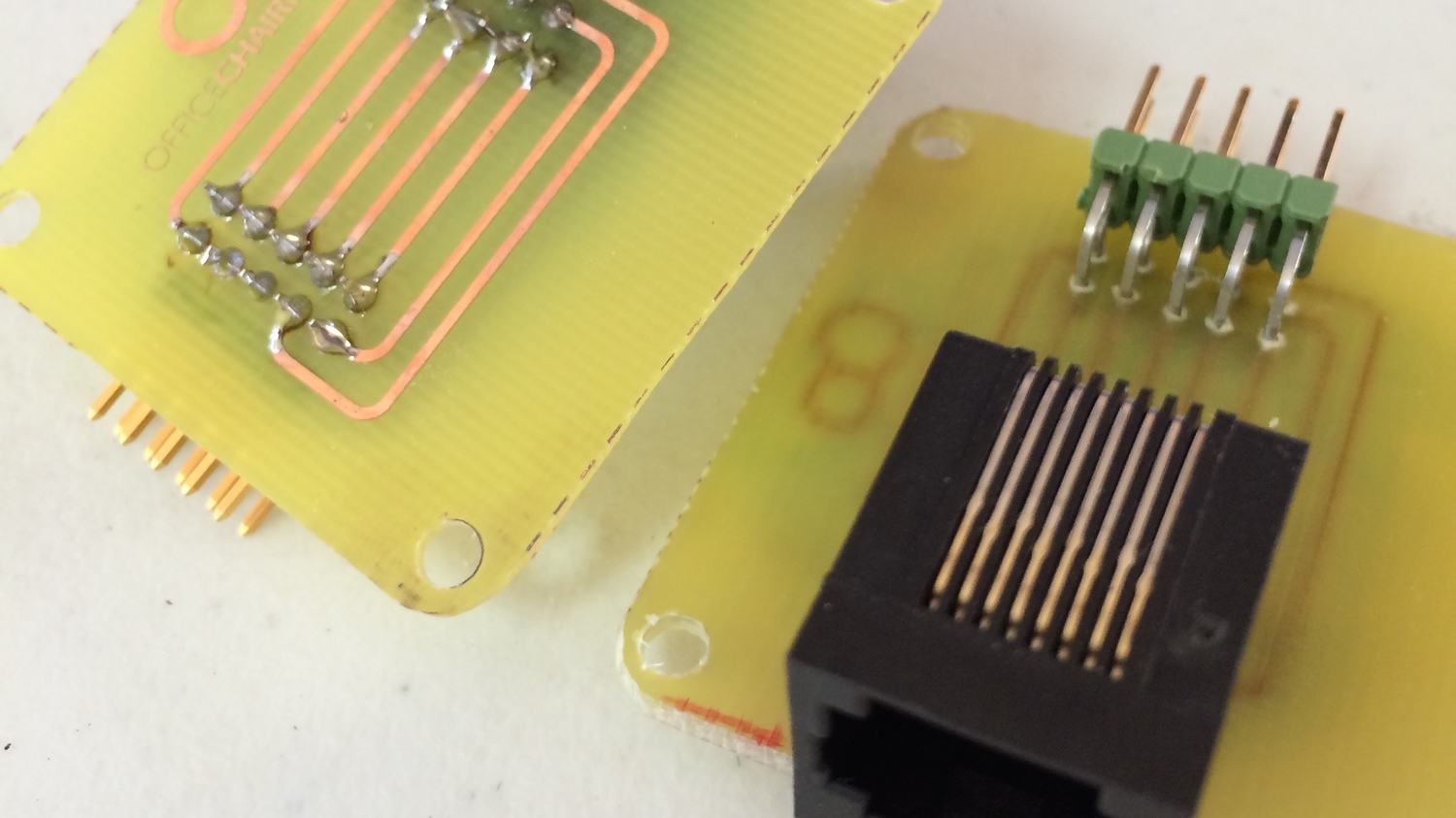
The protocol for communicating with the chassis is very simple and it's even possible (by design) to command the chassis from a terminal application on a desktop computer. Each command is terminated with a newline ('\n') character making it very easy to distinguish between commands as they come in. Every command starts with a command character, such as "M" for motor or "L" for light. What follows that character is dependent upon the context of the first character. Usually, the 2nd character is a more specific target. For example, the "L" command is followed by which particular light you wish to control, such as "L" for the two left turn signals or "H" for the headlights. In the case of the "L" command, the third character is usually either a "1" for "On" or a "0" (zero) for "Off." Some commands take longer numbers, like in the case of RGB LEDs, where a command might look like "LW29485" which means set the "Wunderglow" (under-carriage) RGB LEDs to color 29485 (a 24-bit value representing the red, green and blue values for the pixels).
Here are some examples of commands that can be sent to the SmartChassis Controller:
ML511 = Left motor to idle
MR0 = Right motor to full reverse
MR1023 = Right motor full forward
0 = Both motors full-stop
LH1 = Turn on BOTH headlights
LA1 = Turn on LEFT headlight
LB0 = Turn OFF RIGHT headlight
LL1 = Turn on both LEFT turn signals (front and rear)
LLB = Blink left turn signal
LRB3 = Blink right turn signal 3 times
LC0 = Turn on both headlights
H = Heartbeat (keep-alive character)
SRL = Read left wheel RPMs
STA = Read ambient air temperature
STB = Read left motor temperature
SA = Read accelerometer data (fields returned together)
SG = Read GPS data (fields returned together)
X = Disconnect/exit (shuts down motors and lights)
This protocol will be replaced shortly with a more compact version where targets for actions and whether the action is read or write will be stuffed into bits and the commands will be just a few bytes. This will make the eventual transition to CAN-bus much simpler, as CAN messages usually contain only a handful of bytes. As a side effect, it will make commanding the chassis from a terminal a little more difficult for a human, since we don't tend to pack bits together very well without the help of software or calculators. But, to alleviate that problem, there will be a desktop app for commanding the chassis, as well as an iOS and possibly an Android app (ahead of being able to control the chassis from a mobile device, of course).
An important feature of this system is the safety cut-off for loss of communications with a remote device. As mentioned above, the remote device must stay in contact with the SmartChassis Controller or the controller will shut down the motors and lights. The chassis expects some kind of command, even if it is just an "H" (Heartbeat) command at least every 500 milliseconds. But, before that, a conversation must be started between the two devices. This is accomplished with a simple handshake. Let's walk through the startup sequence:
Chassis 24-volt systems are powered up by connecting the "Master" wire to ground. This energizes the coil in the heavy-duty contactor (big honking relay) and connects power to the motor controller.
The motor controller provides 5 volts for the on-board Arduino, turning it on.
The chassis Arduino opens up its command UART (serial port) and starts sending the string, "Ping!" every second. This is a marker that a potential remote device can look for to make sure the chassis is fully awake and ready to talk.
The control panel (or any remote device) finds the "Ping!" string and now knows that the chassis is waiting for a remote to talk to.
The panel then sends, "Hello!" to the chassis and waits for, "OK" to come back.
If the chassis receives the "Hello!" string intact, it will acknowledge the start of the conversation with, "OK" and comms is now established.
From now until communications is stopped (purposefully or accidentally) the remote must say something to the chassis every 500 ms.
If 500 ms goes by without a word from the remote device, the chassis shuts down the motors and lights and goes back into the waiting mode, sending, "Ping!" over and over again.
If the remote device sends a command other than the handshake while the chassis is in waiting mode, the chassis will send, "NC" (not connected) and go back waiting.
This simple and effective protocol makes accidental disconnects between the chassis and remote devices an "auto-shutdown" kinda situation. This is particularly useful if you're walking alongside the chassis while it's carrying something and you yank the remote cable out of the Remote Port on the chassis. The chassis will stop moving in half a second. This also holds true of wireless connections. If a wireless remote goes out of range or just stops transmitting due to interference or power loss, the chassis stops in its tracks. Conversely, if you simply jack the cable back into the port, the two devices will automatically start talking again, once the remote sees the, "NC" string on its next command attempt. It's a total win-win situation! All the synergies!